Automotive & Transportation•
0★(124 reviews)
The diagram provides a stylized, high-level look at a traditional Contact Point Ignition System. While modern vehicles h
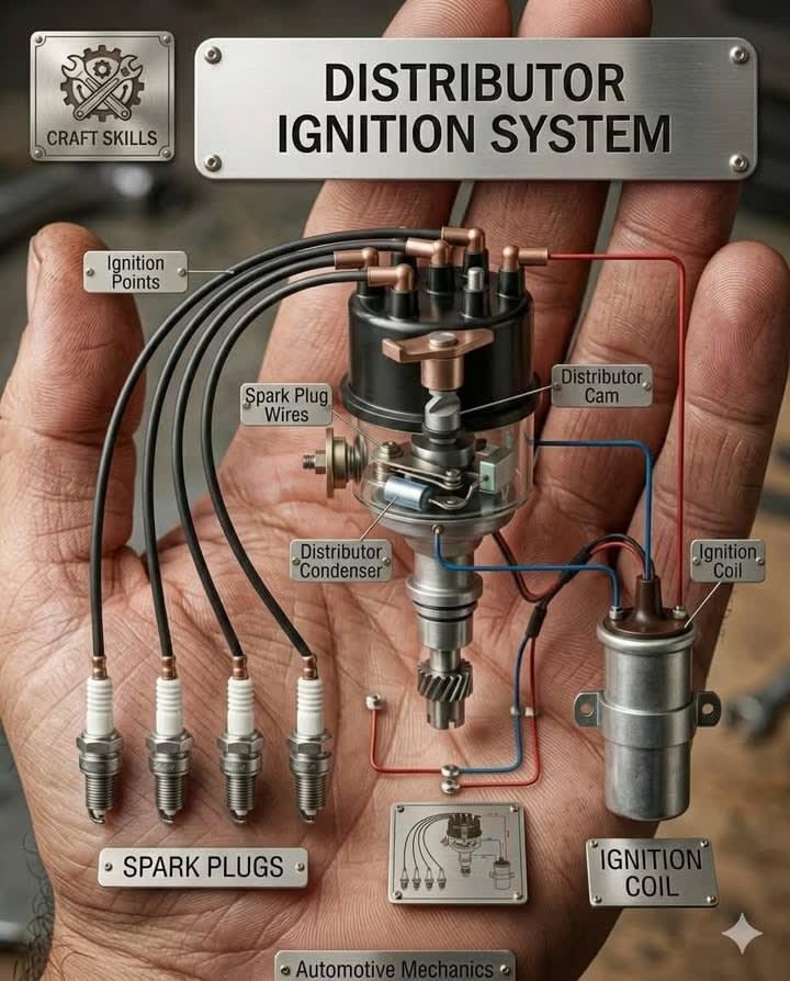
The diagram provides a stylized, high-level look at a traditional Contact Point Ignition System. While modern vehicles have largely moved to Electronic Ignition (EI) or Coil-on-Plug (COP) systems, this mechanical setup was the standard for decades and remains the foundation for understanding engine timing.
𝐇𝐞𝐫𝐞 𝐢𝐬 𝐭𝐡𝐞 𝐦𝐞𝐜𝐡𝐚𝐧𝐢𝐜𝐚𝐥 𝐛𝐫𝐞𝐚𝐤𝐝𝐨𝐰𝐧 𝐨𝐟 𝐡𝐨𝐰 𝐭𝐡𝐢𝐬 𝐬𝐲𝐬𝐭𝐞𝐦 𝐨𝐩𝐞𝐫𝐚𝐭𝐞𝐬 𝐢𝐧 𝐚 𝐫𝐞𝐚𝐥-𝐰𝐨𝐫𝐥𝐝 𝐯𝐞𝐡𝐢𝐜𝐥𝐞.
𝟏. 𝐓𝐡𝐞 𝐄𝐧𝐞𝐫𝐠𝐲 𝐒𝐨𝐮𝐫𝐜𝐞: 𝐓𝐡𝐞 𝐈𝐠𝐧𝐢𝐭𝐢𝐨𝐧 𝐂𝐨𝐢𝐥 The process starts with the Ignition Coil, which acts as a pulse transformer. It takes low-voltage current (usually 12V) from the battery and converts it into the high-voltage (20,000V to 30,000V+) required to jump the gap of a spark plug. Primary Circuit: Low voltage flows through the primary windings, creating a magnetic field. Secondary Circuit: When the primary circuit is suddenly broken, the magnetic field collapses, inducing a massive voltage spike in the secondary windings that travels to the distributor.
𝟐. 𝐓𝐡𝐞 𝐌𝐞𝐜𝐡𝐚𝐧𝐢𝐜𝐚𝐥 𝐇𝐞𝐚𝐫𝐭: 𝐓𝐡𝐞 𝐃𝐢𝐬𝐭𝐫𝐢𝐛𝐮𝐭𝐨𝐫 The distributor is physically geared to the engine's camshaft. This ensures that the "spark" is perfectly synchronized with the position of the pistons. Distributor Cam: As the shaft spins, the lobes on the cam push the Ignition Points open. Ignition Points: These act as a mechanical switch. Every time the points open, the primary circuit is interrupted, triggering the coil to fire. Distributor Condenser (Capacitor): This is a critical fail-safe. It absorbs the electrical "kickback" when the points open, preventing a premature spark (arcing) from burning the points out.
𝟑. 𝐓𝐡𝐞 𝐃𝐢𝐬𝐭𝐫𝐢𝐛𝐮𝐭𝐢𝐨𝐧 𝐏𝐡𝐚𝐬𝐞 Once the coil produces the high-voltage pulse, it travels through a central wire to the center of the Distributor Cap. The Rotor: Inside the cap, a spinning rotor (connected to the distributor shaft) sweeps past internal brass contacts. Spark Plug Wires: The rotor doesn't actually touch the contacts; the high voltage jumps a tiny gap and travels down the specific spark plug wire for the cylinder that is currently on its compression stroke.
𝟒. 𝐓𝐡𝐞 𝐂𝐨𝐦𝐛𝐮𝐬𝐭𝐢𝐨𝐧: 𝐒𝐩𝐚𝐫𝐤 𝐏𝐥𝐮𝐠𝐬 The high-voltage pulse reaches the Spark Plug, where it forced to jump a final gap between the center electrode and the ground electrode. This "arc" creates the spark that ignites the compressed air-fuel mixture, forcing the piston down and creating power.
Comparison: Mechanical vs. Modern In a real vehicle today, you likely won't see "points" or a "condenser."
_Price: Contact Amya Motors for price._
Ksh 1
Free shipping on orders over Ksh 50
A
Sold by Amya Motors LTD
★★★★★Trusted Vendor
Felba Assistant
Guest guidance for this page
1
In Stock: Yes
Share this product
Key Features
- Premium quality materials
- 12-month warranty
- Free returns within 30 days
- Eco-friendly packaging
product.productDescription
The diagram provides a stylized, high-level look at a traditional Contact Point Ignition System. While modern vehicles have largely moved to Electronic Ignition (EI) or Coil-on-Plug (COP) systems, this mechanical setup was the standard for decades and remains the foundation for understanding engine timing. 𝐇𝐞𝐫𝐞 𝐢𝐬 𝐭𝐡𝐞 𝐦𝐞𝐜𝐡𝐚𝐧𝐢𝐜𝐚𝐥 𝐛𝐫𝐞𝐚𝐤𝐝𝐨𝐰𝐧 𝐨𝐟 𝐡𝐨𝐰 𝐭𝐡𝐢𝐬 𝐬𝐲𝐬𝐭𝐞𝐦 𝐨𝐩𝐞𝐫𝐚𝐭𝐞𝐬 𝐢𝐧 𝐚 𝐫𝐞𝐚𝐥-𝐰𝐨𝐫𝐥𝐝 𝐯𝐞𝐡𝐢𝐜𝐥𝐞. 𝟏. 𝐓𝐡𝐞 𝐄𝐧𝐞𝐫𝐠𝐲 𝐒𝐨𝐮𝐫𝐜𝐞: 𝐓𝐡𝐞 𝐈𝐠𝐧𝐢𝐭𝐢𝐨𝐧 𝐂𝐨𝐢𝐥 The process starts with the Ignition Coil, which acts as a pulse transformer. It takes low-voltage current (usually 12V) from the battery and converts it into the high-voltage (20,000V to 30,000V+) required to jump the gap of a spark plug. Primary Circuit: Low voltage flows through the primary windings, creating a magnetic field. Secondary Circuit: When the primary circuit is suddenly broken, the magnetic field collapses, inducing a massive voltage spike in the secondary windings that travels to the distributor. 𝟐. 𝐓𝐡𝐞 𝐌𝐞𝐜𝐡𝐚𝐧𝐢𝐜𝐚𝐥 𝐇𝐞𝐚𝐫𝐭: 𝐓𝐡𝐞 𝐃𝐢𝐬𝐭𝐫𝐢𝐛𝐮𝐭𝐨𝐫 The distributor is physically geared to the engine's camshaft. This ensures that the "spark" is perfectly synchronized with the position of the pistons. Distributor Cam: As the shaft spins, the lobes on the cam push the Ignition Points open. Ignition Points: These act as a mechanical switch. Every time the points open, the primary circuit is interrupted, triggering the coil to fire. Distributor Condenser (Capacitor): This is a critical fail-safe. It absorbs the electrical "kickback" when the points open, preventing a premature spark (arcing) from burning the points out. 𝟑. 𝐓𝐡𝐞 𝐃𝐢𝐬𝐭𝐫𝐢𝐛𝐮𝐭𝐢𝐨𝐧 𝐏𝐡𝐚𝐬𝐞 Once the coil produces the high-voltage pulse, it travels through a central wire to the center of the Distributor Cap. The Rotor: Inside the cap, a spinning rotor (connected to the distributor shaft) sweeps past internal brass contacts. Spark Plug Wires: The rotor doesn't actually touch the contacts; the high voltage jumps a tiny gap and travels down the specific spark plug wire for the cylinder that is currently on its compression stroke. 𝟒. 𝐓𝐡𝐞 𝐂𝐨𝐦𝐛𝐮𝐬𝐭𝐢𝐨𝐧: 𝐒𝐩𝐚𝐫𝐤 𝐏𝐥𝐮𝐠𝐬 The high-voltage pulse reaches the Spark Plug, where it forced to jump a final gap between the center electrode and the ground electrode. This "arc" creates the spark that ignites the compressed air-fuel mixture, forcing the piston down and creating power. Comparison: Mechanical vs. Modern In a real vehicle today, you likely won't see "points" or a "condenser." _Price: Contact Amya Motors for price._